What is a CAN Bus? How it impacts fleet management
December 1, 2025
•6 minute read
Definition
- The CAN bus (Controller Area Network) is a core component of modern vehicle electronics, allowing electronic control units to exchange data without a central computer.
- CAN bus diagnostics monitor key vehicle metrics (e.g., engine temperature, oil pressure, transmission performance and brake health) in real time to prevent costly downtimes.
- Fleet operators use CAN bus data to get actionable insights on fuel use, driver behavior and vehicle performance to improve routing optimization and idle time.
The Controller Area Network (CAN) bus is a communication system that connects a vehicle’s electronic control units (ECUs), allowing fleet telematics systems to directly access detailed data on everything from fuel consumption to brake wear.
Modern fleet operations use CAN bus to make data-driven decisions, tracking maintenance needs before failures occur, identifying fuel-inefficient driving behaviors and optimizing routes based on performance metrics. If used correctly, CAN bus data can be a big help with maintenance costs and improving fuel efficiency.
In this post, we’ll explore how CAN bus data supports predictive maintenance, improves fuel efficiency and helps fleet operators manage more efficiently.
What is CAN bus?
What exactly is CAN bus? The Controller Area Network (CAN) bus is a message-based communication protocol made to allow electronic control units and microcontrollers inside of vehicles to reliably exchange information without a central host computer. It enables dozens of vehicle systems to share data across a single, two-tier network.
Think of it this way: The CAN bus is a digital highway where each electronic component in a vehicle can drive messages to any other component. Unlike traditional point-to-point wiring, in which each system is connected separately, the CAN bus system uses shared communication pathways, with each message carrying a priority identifier.
Modern vehicles use different types of CAN bus cables depending on the application. High-speed CAN operates up to 1 Mbps for time-critical systems like powertrain control, while low-speed, fault-tolerant CAN runs at 125 kbps for convenience features. The newer CAN FD (Flexible Data Rate) standard also permits faster data transfer when needed.
A brief history of CAN bus
In 1983, Robert Bosch worked with Mercedes-Benz engineers and Intel to develop the initial stages of CAN bus development. The goal was to create new vehicle functionalities to improve automotive reliability and meet real-time requirements. Bosch officially introduced the CAN protocol at the Society of Automotive Engineers (SAE) Congress in Detroit in 1986.
The 1991 Mercedes-Benz W140 became the first production vehicle to feature CAN-based multiplex wiring systems, and by the mid-1990s automotive manufacturers worldwide adopted CAN as the standard for in-vehicle networking. Today, CAN bus protocol extends past the automotive industry into medical devices, maritime systems and more.
How CAN bus works
The CAN bus system uses a broadcast communication model in which all connected electronic control units share a common two-wire network. Modern CAN uses CAN FD (flexible data rate), which can transmit larger payloads (up to 64 bytes compared to the classic version’s 8 bytes), and can achieve much higher data rates with bit rate switching.
CAN bus architecture
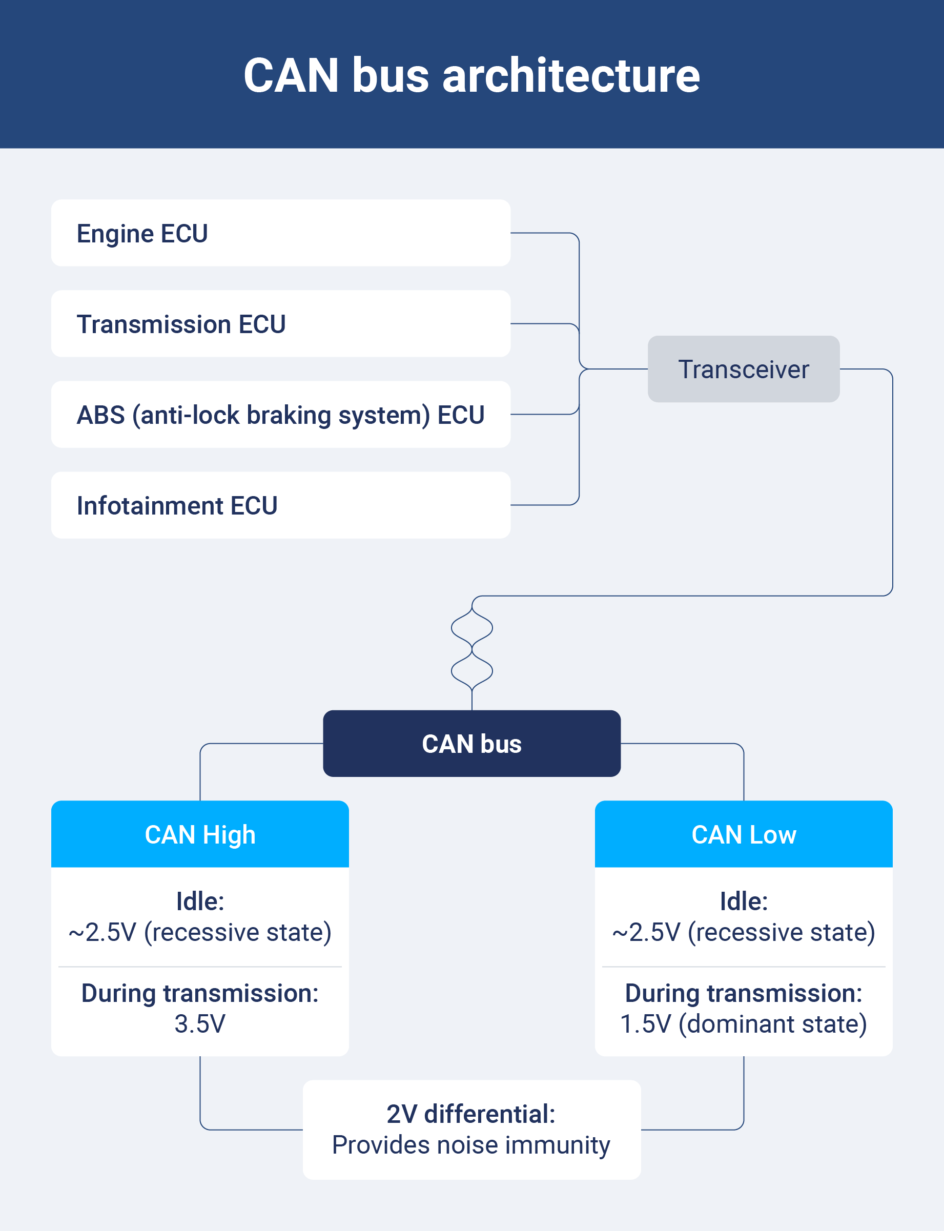
The physical architecture of CAN bus is made up of nodes called electronic control units (ECUs), a twisted-pair cable and transceivers that interface between analog bus signals and digital controllers. Each node contains a CAN controller managing protocol timing and a transceiver converting between the controller’s digital signals and the bus’s differential voltage levels.
Here is how this works in a modern vehicle. When a bus idles, both CAN High and CAN Low sit at about 2.5 volts. A recessive state means availability. During transmission, the transceiver drives CAN High to 3.5 volts and CAN Low to 1.5 volts.
That 2-volt differential represents a dominant state. This differential signalling provides noise immunity, which is especially important when driving in harsh environments.
Messaging basics
Communication occurs through structured data frames and contains an identifier, control information, data payload, error checking and acknowledgement fields.
The identifier indicates message content and establishes priority. Lower identifier values win arbitration so time-critical safety messages take priority over non-urgent information.
How does this system handle errors? If a node detects any error, it broadcasts an error frame, forcing all transmitters to halt and retry. Error handling mechanisms use cyclic redundancy, verifying data integrity and bit stuffing to prevent synchronization errors.
CAN OSI model overview
The CAN bus protocol maps to the two lowest layers of a seven-layer OSI (Open Systems Interconnection) reference model, which is used to describe network communications. ISO 11898-1 defines the data link layer, error handling and how nodes manage bus access. ISO 11898-2 and ISO 118998-3 define physical layer specifications and priorities.
This layered architecture allows the core CAN protocol to remain stable and hardware-independent, leaving higher-layer protocols to address domain-specific requirements.
CAN FD (flexible data rate)
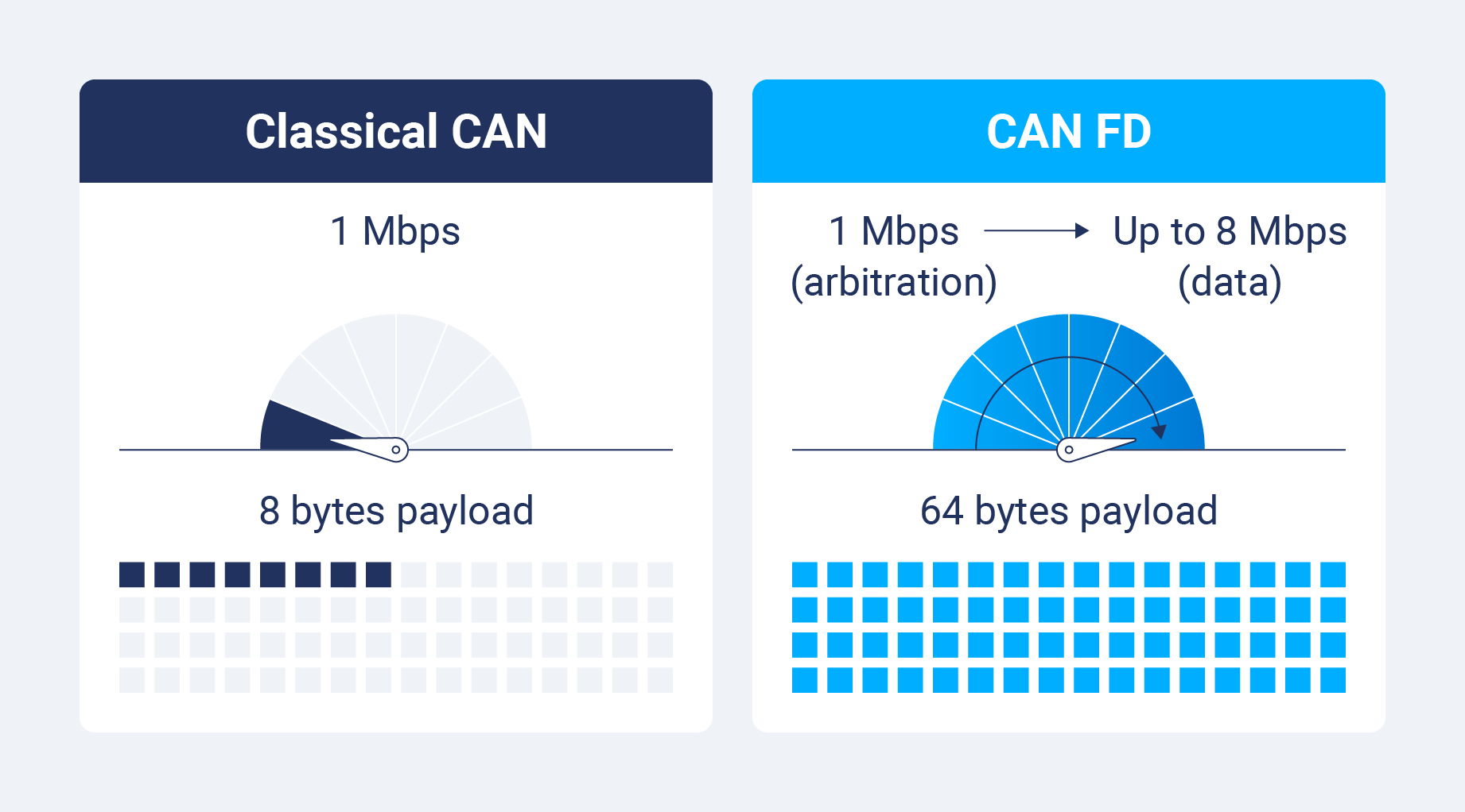
CAN FD is how Classical CAN evolved to meet modern bandwidth demands without leaving behind the original architecture. This change used dynamic bit rate switching within individual frames.
Here is exactly how that works: arbitration takes place at conventional speeds up to 1 Mbps, and the data transmission phase accelerates to 2, 5 or 8 Mbps depending on network capabilities. Payload capability expands from 8 to 64 bytes per frame, giving protocol efficiency a massive boost by cutting back on overheard.
Benefits of CAN bus
The controller area network transformed commercial vehicle operations thanks to simplified architecture, improved reliability and data accessibility. Other benefits include:
- Reduced wiring capacity: The CAN bus system eliminates the requirements of traditional point-to-point wiring by allowing dozens of ECUs to share a single two-wire network, cutting back on vehicle weight and improving fuel efficiency.
- Real-time communication: Prioritized messaging means critical data reaches recipients within microseconds, regardless of network traffic.
- Fault tolerance and reliability: Comprehensive error detection is designed to catch problems before corrupted data impacts vehicle operation, with each node independently validating received messages via CRC checks, bit monitoring and acknowledgement verification.
- Standardized diagnostics: OBD-II ports provide direct access to CAN bus data so technicians can retrieve diagnostic trouble codes and verify repair effectiveness. This standardization means maintaining a fleet is as simple as using a single scan tool to diagnose an entire fleet, regardless of fleet diversity.
- Cost effectiveness: CAN bus protocol reduces long-term maintenance costs with simplified architecture and improved diagnostics, and its broadcast nature also improves reliability — if one node fails, the rest of the network continues to operate.
The future of CAN bus in fleet management
CAN bus data and cloud-based, AI-powered telematics platforms are transforming fleet management from reactive to predictive, making data-driven business decisions commonplace.
Real-time vehicle monitoring for predictive maintenance
Modern fleet management systems can detect subtle performance degradation from hundreds of CAN bus parameters, watching for anything from transmission temperature changes, engine oil pressure declines and diesel particulate filter pressure differential rises. This predictive approach takes fleet maintenance from reactive emergencies to well-prepared plans.
Reduced maintenance costs and downtime
Access to granular CAN bus diagnostics means there is no need for diagnostic guesswork or risking unnecessary part replacement. If a vehicle has a check engine light, technicians immediately review stored diagnostic trouble codes. They can even look at detailed freeze frame data captures to see operating conditions when the fault occurred.
Fleet managers receive automatic alerts when monitored parameters exceed standard ranges, sometimes weeks before drivers even notice symptoms. That means your maintenance schedules can be based on actual component condition, not just arbitrary time or mileage intervals, extending parts and vehicle life and preventing unexpected breakdowns.
Fault tolerance and reliability for commercial vehicles
Commercial vehicle CAN networks use redundant architecture so critical systems maintain operations even during component failures. Heavy-duty vehicles often use multiple CAN buses across chassis, body and information systems, so if one BUS experiences failures, the other systems can continue.
This resilience is critical for fleet operations, especially in remote areas where breakdowns are a costly risk.
Integration with telematics and fleet management systems
CAN bus decoders combined with GPS telematics devices mean you get a comprehensive vehicle intelligence program: fuel consumption, GPS location, route information and inefficient driver behaviors data all become easy to review in real-time time.
This data improves driver performance and route optimization. Overall fleet performance is further improved through reduced idle time, extended vehicle lifespan and minimized fuel waste.
Access to this level of deeper data means you can analyze things like brake activation frequency relative to routes to improve brake service intervals and prevent premature wear.
How to use CAN bus data
CAN bus data is only as useful as you make it. To extract actionable intelligence, you need the right tools, decoding techniques and a systematic troubleshooting approach.
Fleet telematics devices connect to vehicles with OBD-II ports or direct CAN bus taps, capturing raw message frames for transmission to cloud-based management platforms. A CAN bus decoder interprets the raw information and maps it to human-readable parameters, translating hexadecimal data into meaningful metrics like engine temperature and more.
Get started with decoding by following these steps:
- Figure out the CAN protocol variant and bit rate used by your target vehicle. Most commercial trucks use J1939 running at 259 kbps.
- Connect logging hardware to the vehicle’s diagnostic port or directly to CAN High and CAN Low wires at any ECU connector.
- Capture a data sample during normal operations, then analyze message identifiers to determine which ECUs are transmitting.
- Cross-reference your captured identifiers against manufacturer-specific DBC files or industry-standard parameter definitions so you can decode the message’s content.
Harness the power of fleet data with Geotab
The CAN bus offers enormous value when properly harnessed with the right telematics platforms. It takes raw vehicle data and turns it into strategic vehicle intelligence. Geotab’s advanced fleet data analytics tools decode CAN protocols automatically, getting fleet managers technical insights without any specialized technical expertise.
The true value of CAN bus and telematics is clear in the cost reductions. Fuel optimization programs use real-time consumption data and can improve gas mileage by about 10%. But the true value extends past even that, with CAN bus data making it easy to make fleet rightsizing decisions, guide replacement timing and support sustainability initiatives.
Geotab’s electronic logging device (ELD) solution has a commitment to data ethics, meaning any fleet data you find generates business value while respecting driver privacy and regulatory requirements. This specialized ethical framework builds driver trust essential for program success, all while ensuring compliance.
Learn how Geotab’s ELD solution can help your fleet perform more efficiently — and responsibly.
Frequently Asked Questions
A CAN bus enables electronic control units inside a vehicle to exchange information without a central host computer, improving communication efficiency. Automotive applications include engine management systems, anti-lock braking systems and climate systems based on engine pressure.
CAN bus failure takes place when communications between electronic control units degrade or cease, preventing critical vehicle systems from exchanging data. Common failure modes include physical wiring damage that causes opens or shorts, failed termination resistors, corroded connectors or malfunctioning ECU transceivers.
Any vehicle manufactured after 2008 has CAN bus networks, as OBD-II regulations require CAN for emission diagnostics on all vehicles sold in the US after January 2008. European vehicles adopted CAN mandates earlier. Check if your car has a CAN bus by looking for an OBD-II port (usually under the dashboard) with 16 pins.
Other Stories
What is telemetry? How it works and why fleets need it
December 24, 2025
4 minute read
August 5, 2025
5 minute read
July 17, 2025
4 minute read